
Physics · chapter PYQs
Semiconductor Electronics, on the exam screen.
8 questions from NEET 2026, Re-NEET 2026, NEET 2020, 8 minutes, marked +4 / −1. See them with solutions.
Semiconductor Electronics · PYQs
Candidate: You
Time Left
Q1/8
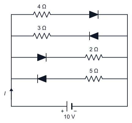
The current in the circuit shown below is: (All diodes are ideal and identical)
Answer and explanation
Answer: (4)
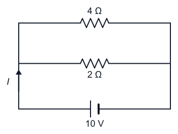
An ideal diode has zero forward resistance and infinite reverse resistance, so only the branches whose diodes are forward biased conduct; here that leaves the 4 and 2 resistors in parallel across the 10 V battery. The current is A, giving (4). The other options wrongly include the reverse-biased 3 and 5 branches that actually carry no current.
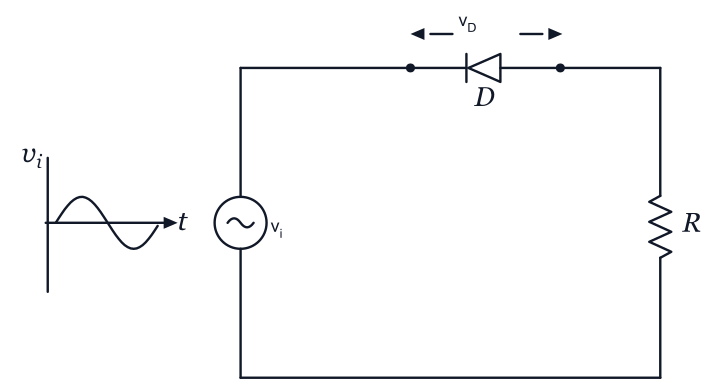
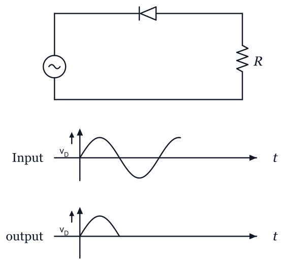
In the circuit shown below, the voltage appearing across the diode will be of the form:
Answer and explanation
Answer: (4)
The applied alternating current (ac) voltage drives current through the diode and R in series. During the half-cycle that reverse-biases the diode, almost the entire source voltage appears across the non-conducting diode, whereas in the forward-biased half-cycle the diode drop is nearly zero. So consists of one-sided humps with flat (near-zero) gaps, matching option (4). A full sine or a double-hump trace would wrongly imply the diode never blocks the current.
Two statements are given below. Choose the correct answer from the options given below.
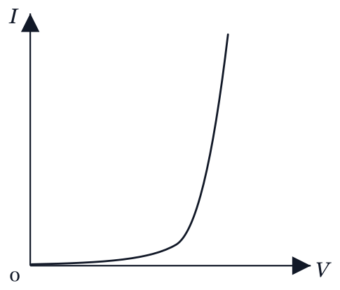
I. A. When the forward bias voltage across a p-n junction diode increases above a certain threshold voltage, the diode current increases significantly.
II. B. This current is called reverse saturation current.Answer and explanation
Answer: (2)
Statement A is correct: beyond the threshold (knee) voltage in forward bias, the diode current rises steeply, as seen in the forward V-I characteristic. Statement B is wrong: this rapidly increasing current is the forward current, whereas reverse saturation current is the very small, nearly constant current that flows under reverse bias.
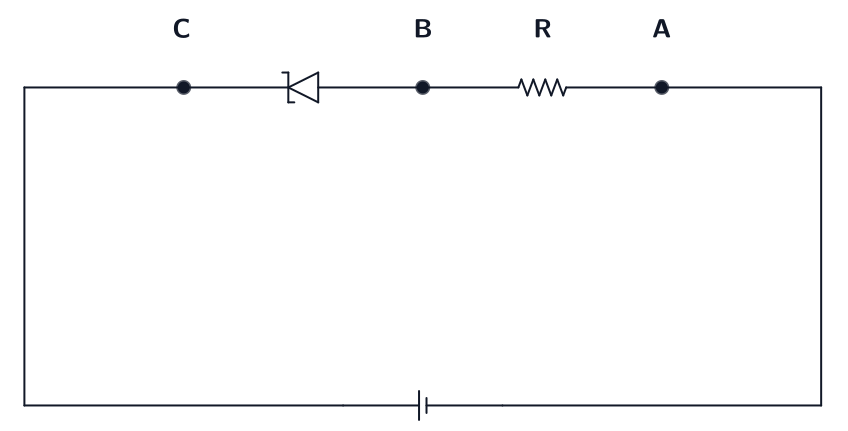
An ideal Zener diode with breakdown voltage of -3 V is reverse biased with a negative input voltage . The magnitude of voltage difference between point and is:
Answer and explanation
Answer: (2)
Once an ideal Zener diode is driven past its breakdown voltage it CLAMPS the voltage across itself at 3 V and behaves like a constant-voltage source. The remaining of the supply must therefore appear across the series resistor, which is the element between and . NCERT Class 12, Semiconductor Electronics (Zener diode as a voltage regulator).
Why the other options are wrong:
- (1) reports the voltage across the ZENER rather than across the resistor between and
- (3) subtracts twice, or assumes the diode drops an extra 1 V forward-bias contribution
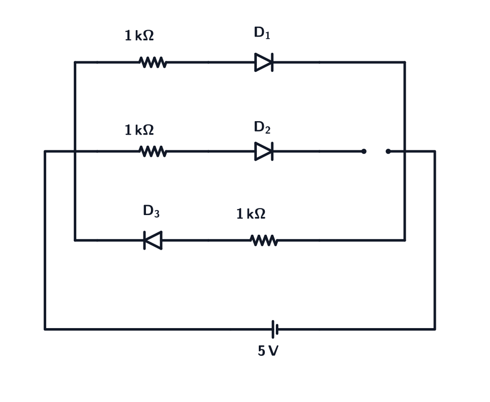
- (4) assumes the reverse-biased diode blocks all current, so no drop appears across the resistor - but breakdown means current does flowThree identical p-n junction diodes , , and are connected across a battery as shown in the figure. If the width of the depletion regions of , and are , and , respectively, then the correct option is:
Answer and explanation
Answer: (3)
Depletion width is set by the net potential barrier at the junction. Forward bias lowers the barrier and NARROWS the depletion layer; reverse bias raises it and WIDENS the layer; an unbiased junction sits at its equilibrium width in between. In this circuit is forward biased (narrowest), 's branch carries no bias so it keeps its equilibrium width, and is reverse biased (widest), giving . NCERT Class 12, Semiconductor Electronics (p-n junction).
Why the other options are wrong:
- (1) reverses the bias effect, assuming forward bias widens and reverse bias narrows the depletion region
- (2) assumes forward and reverse bias shift the width by equal and opposite amounts so that and coincide
- (4) treats the unbiased diode as the extreme case rather than the intermediate oneThe increase in the width of the depletion region in a p-n junction diode is due to :
Answer and explanation
Answer: (1)
The width of the depletion region increases under reverse bias, as the applied voltage enhances the electric field and repels more majority carriers away from the junction. Chapter: Semiconductor Electronics.
For transistor action, which of the following statements is correct?
Answer and explanation
Answer: (3)
For transistor action, the base region must be very thin and lightly doped to ensure that most of the charge carriers injected from the emitter reach the collector. Chapter: Semiconductor Electronics.
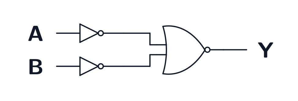
For the logic circuit shown, the truth table is
Answer and explanation
Answer: (4)
Each input passes through a NOT gate, and the two inverted inputs feed a NOT-OR (NOR) gate, so Y = NOT(NOT A OR NOT B), which simplifies to A AND B. The circuit is therefore an AND gate, whose output is high only when both inputs are high:
A
B
Y
0
0
0
0
1
0
1
0
0
1
1
1
Chapter: Semiconductor Electronics.
Why the other options are wrong:
- (1) This is the OR truth table: it makes Y high whenever either input is high, which the inverters plus NOR does not do.
- (2) This is the NOT-AND (NAND) truth table, the inverse of the correct one. It would follow from an AND gate with an inverted output.
- (3) This is the NOR truth table, which is what a single NOR gate gives for A and B directly, without the two inverters.
Your result
0 / 32
Keep practising with NEET PYQs, review explanations and track your chapter accuracy in the app. Free until the 2027 exam.