

Current Electricity: NEET previous year questions
Every Current Electricity question from the official NEET papers on this site, with the answer and a worked solution.
The questions come from NEET 2026, Re-NEET 2026 and NEET 2020. Each shows its answer and solution when you open it, so you can attempt it first. For what the chapter covers and how NEET tests it, see the Current Electricity guide.
NEET 2026
NEET 2026 · Q6
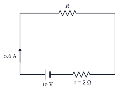
A resistor is connected to a battery of 12 V emf and internal resistance 2 . If the current in the circuit is 0.6 A, the terminal voltage of the battery is:
- (1)
10 V
- (2)
1.2 V
- (3)
12 V
- (4)
10.8 V
Answer and solution
Answer: (4)
The terminal voltage is the electromotive force (emf) minus the drop across the internal resistance: V, option (4). The 1.2 V drop across the internal resistance is what is subtracted, and 12 V would only be the terminal voltage if no current flowed.
- (1)
NEET 2026 · Q27
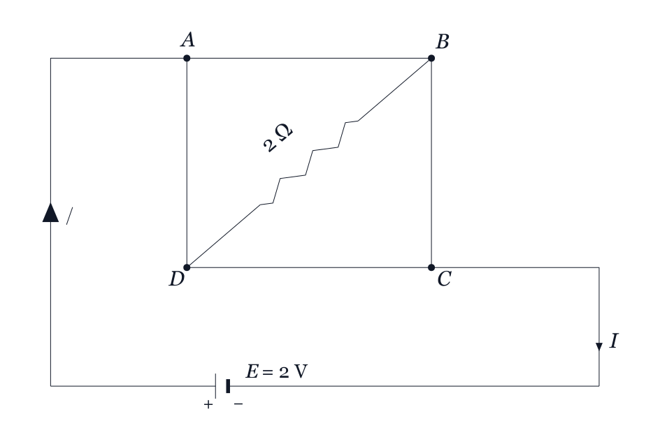
A uniform metallic wire having resistance 4 is bent to form a square loop (ABCD) (see figure). A resistance of 2 is connected between points B and D and a battery of 2 V is connected across points A and C as shown in the figure. Now the value of current () is:
- (1)
2 A
- (2)
8 A
- (3)
4.5 A
- (4)
4 A
Answer and solution
Answer: (1)
The 4 wire splits equally, so each side of the square is 1 . With the 2 across diagonal BD and the 2 V battery across A and C, the four 1 arms form a balanced Wheatstone bridge, so no current flows through the 2 branch. The effective resistance across AC is 1 , giving A.
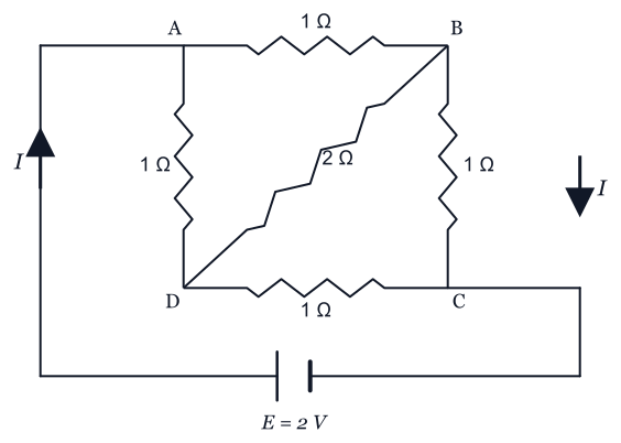
Why the other options are wrong:
- (2) Assumes far too low a resistance.
- (3) Arbitrary value from mis-combining resistances.
- (4) Would need 0.5 , as if each path from A to C had one 1 side instead of two.- (1)
NEET 2026 · Q28
A room heater is rated 400 W, 220 V. If the supply voltage drops to 200 V, what will be the power consumed (approximately)?
- (1)
200 W
- (2)
400 W
- (3)
331 W
- (4)
121 W
Answer and solution
Answer: (3)
The heater resistance is fixed, so gives W. Power scales as the square of voltage, not linearly, so option (2) (unchanged) and option (1) (linear scaling) are wrong, and option (4) over-reduces.
- (1)
NEET 2026 · Q37
In a metre bridge experiment (see figure), the positions of the cell, , and galvanometer, , are interchanged. We shall observe in the galvanometer:

- (1)
Only the left-sided deflection
- (2)
There will be no deflection irrespective of the position of the jockey
- (3)
Only the right-sided deflection
- (4)
Both right-sided and left-sided deflection and at balance point, no deflection
Answer and solution
Answer: (4)
A metre bridge is a Wheatstone network, whose balance (null) condition is symmetric with respect to interchanging the cell and the galvanometer, so the balance point does not move. Away from that point the bridge is unbalanced and the galvanometer deflects; the direction of deflection depends on which side of balance the jockey lies, and it reads zero exactly at the balance point.
Why the other options are wrong:
- (1) Deflection is not restricted to one side; it flips about the null point.
- (2) No deflection occurs only at balance, not everywhere.
- (3) Same error as (1) but for the opposite side.- (1)
Re-NEET 2026
Re-NEET 2026 · Q36
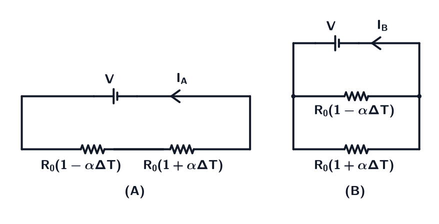
Consider two circuits, (A) and (B), each having two resistors. One of them has a positive temperature coefficient of resistance, , while the other one has a negative temperature of coefficient, , as shown in the figure. The current through these circuits are denoted by and . At initial temperature, the resistance of the two resistors is . As the temperature is increased, the correct option that describes the variation of current in these circuits is:
- (1)
remains constant while increases
- (2)
decreases while increases
- (3)
increases while decreases
- (4)
Both and remain constant
Answer and solution
Answer: (1)
In circuit (A) the resistors are in SERIES, so - the two temperature terms cancel exactly and is unchanged. In circuit (B) they are in PARALLEL, giving , which decreases as grows because of the term, so increases. NCERT Class 12, Current Electricity (temperature dependence of resistivity).
Why the other options are wrong:
- (2) assumes the series combination must heat up and resist more, missing the exact cancellation between and
- (3) swaps the two circuits, applying the parallel result to (A) and the series result to (B)
- (4) spots the cancellation in series and wrongly assumes the same cancellation holds for reciprocals in parallel- (1)
NEET 2020
NEET 2020 · Q145
Which of the following graph represents the variation of resistivity (ρ) with temperature (T) for copper?
- (1)
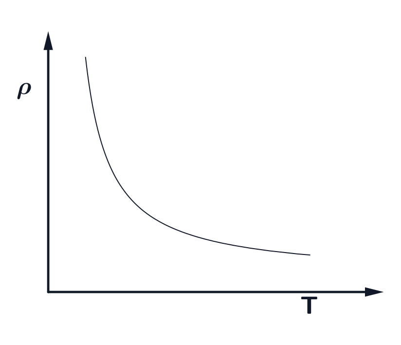
- (2)
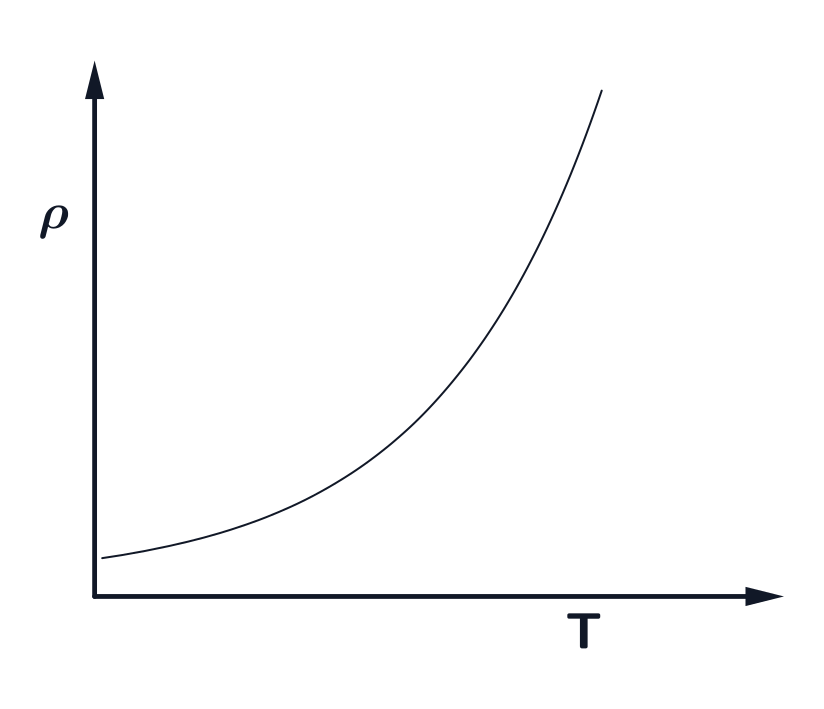
- (3)
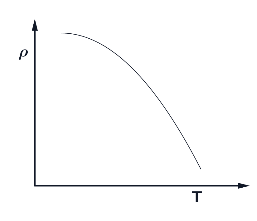
- (4)
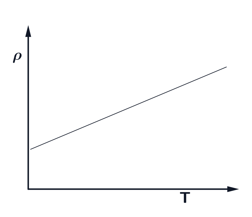
Answer and solution
Answer: (2)
For copper, resistivity rises with temperature and is nearly linear over a limited ordinary-temperature range, but bends appreciably at very low temperatures. The source curve with that behaviour is option (2). Chapter: Current Electricity.
Why the other options are wrong:
- (1) Resistivity falling steeply and then levelling off as temperature rises is how a semiconductor behaves, not a metal like copper.
- (3) This curve shows resistivity decreasing with temperature, but the resistivity of copper increases with temperature.
- (4) A straight line treats copper as linear at every temperature, but the linear relation holds only over a limited range and the real curve bends at low temperatures.- (1)
NEET 2020 · Q162
The color code of a resistance is given below
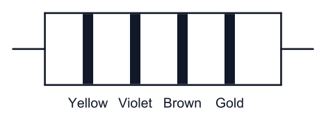
The values of resistance and tolerance, respectively, are
- (1)
47 k, 10%
- (2)
4.7 k, 5%
- (3)
470 , 5%
- (4)
470 k, 5%
Answer and solution
Answer: (3)
Yellow and violet give digits 4 and 7, brown is the ×10 multiplier, and gold means 5%. Therefore R = with 5% tolerance. Chapter: Current Electricity.
Why the other options are wrong:
- (1) 47 k would need an orange () multiplier band, and 10% tolerance is a silver band, not gold.
- (2) 4.7 k is , which needs a red multiplier band; brown only multiplies by 10.
- (4) 470 k is , which needs a yellow multiplier band; brown only multiplies by 10.- (1)
NEET 2020 · Q166
A resistance wire connected in the left gap of a metre bridge balances a 10 resistance in the right gap at a point which divides the bridge wire in the ratio 3 : 2. If the length of the resistance wire is 1.5 m, then the length of 1 of the resistance wire is :
- (1)
m
- (2)
m
- (3)
m
- (4)
m
Answer and solution
Answer: (1)
At balance, R/10 = 3/2, so the 1.5 m resistance wire has R = 15 . Its length per ohm is 1.5/15 = 0.10 m. Chapter: Current Electricity.
- (1)
NEET 2020 · Q169
A charged particle having drift velocity of 7.5 × 10⁻⁴ m s⁻¹ in an electric field of 3 × 10⁻¹⁰ V m⁻¹ has a mobility in m² V⁻¹ s⁻¹ of
- (1)
- (2)
- (3)
- (4)
Answer and solution
Answer: (1)
Mobility is given by , where is the drift velocity and is the electric field. Substituting the values, . Chapter: Current Electricity.
- (1)
NEET 2020 · Q179
The solids which have the negative temperature coefficient of resistance are:
- (1)
insulators only
- (2)
semiconductors only
- (3)
insulators and semiconductors
- (4)
metals
Answer and solution
Answer: (3)
Metals have a positive temperature coefficient of resistance, while insulators and semiconductors have a negative temperature coefficient of resistance. This is due to the increase in carrier concentration in insulators and semiconductors with temperature. Chapter: Current Electricity.
- (1)
Practise Current Electricity in the app: it brings back the questions you get wrong, so the chapter improves, not just your memory of these. Or try the free CBT mock. All chapters: NEET chapter-wise PYQs.
Questions
Are these the official NEET questions on Current Electricity?
Yes. They are the questions NTA set in each paper, in its wording. The solutions are written by BrainIt.
Something here wrong or out of date? Email hello@brainit.pro and a person will read it.